Drywall profiles
High-quality drywall profiles for every application
Material legend
Profiles and accessories for wall systems
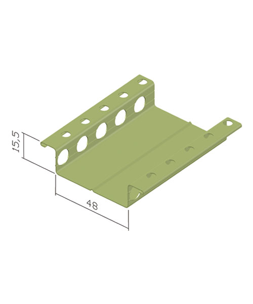

Profiles for drywall construction


End profiles for plasterboard
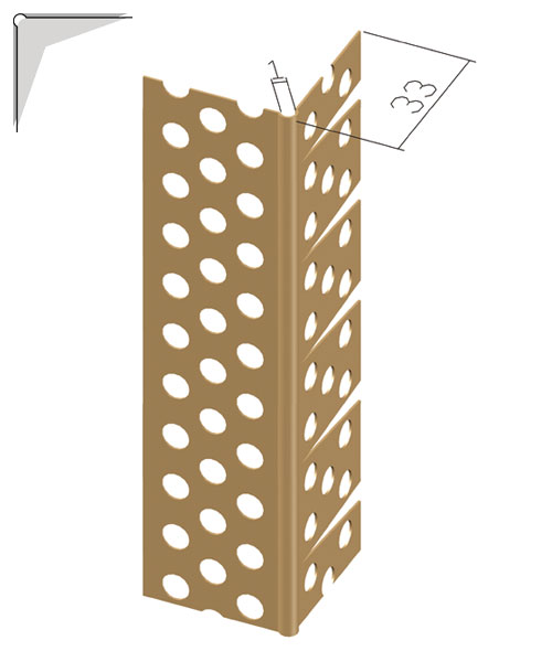
Edging profiles for plasterboard
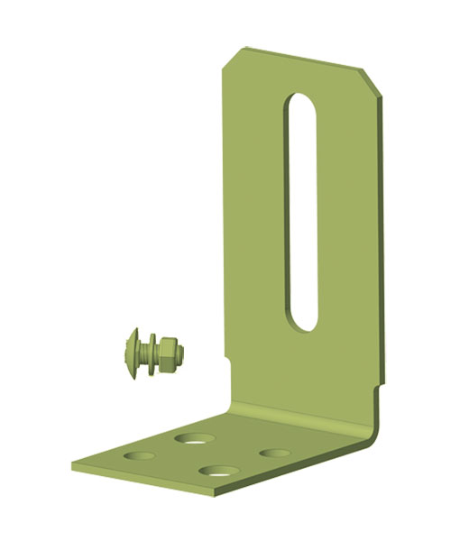
Profiles and accessories for substructures with plasterboard


Product information
- Use a laser or spirit level to determine the course of the ceiling.
Select the fixing points after determining the type of installation (board type and thickness, transverse or longitudinal installation of the plasterboard to the CD support profile) and then mark the ceiling. - Attachment of UD edge profile Art. no.: 71300, 71499 using dowels in the wall area.
- Attach suspension wires or nonius upper sections of the desired length to the ceiling at the marking points and bend vertically downwards.
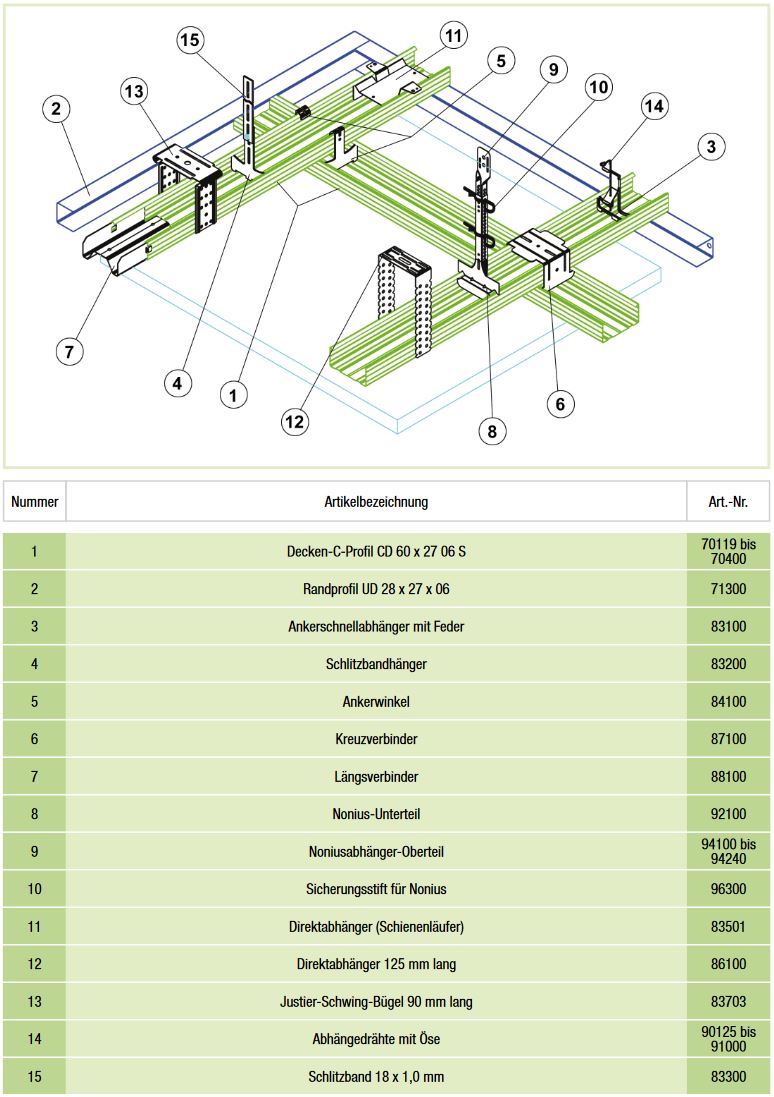
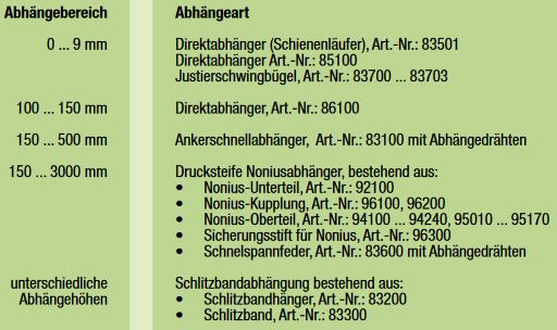
- Insert the hangers into the CD support profile, item no. 70119 to 70400, with the following recommended suspension options:
5. place the CD support profiles on the top of the UD edge profile.
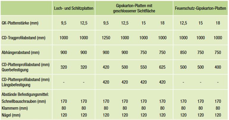
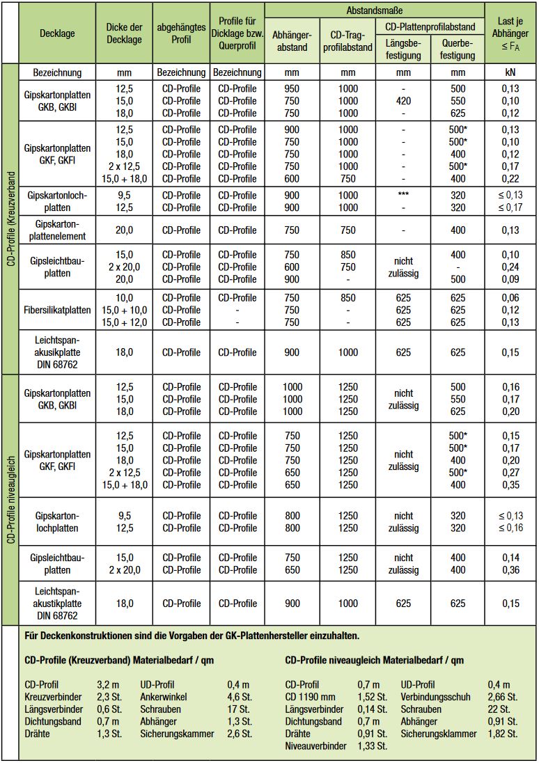
Please also refer to the installation table for the center distance of the CD support profile from the wall or from support profile to support profile depending on the panel type and thickness.
6. once the CD support profiles have been adjusted, the CD panel profile, art. no.: 70119 to 70400, is connected crosswise using cross quick connectors, art. no.: 87100 or anchor bracket, art. no.: 84100 (angle anchor to be bent with pliers). The CD panel profiles are inserted into the UD edge profile.
The distances between the CD board profiles can also be found in the table Installation instructions according to DIN 18181. Profile joints are connected with the longitudinal connector, Art. no.: 88100 and arranged in a staggered manner. An additional hanger must be arranged at the profile joint for CD support profiles.
7. attach the plasterboard transversely or longitudinally to the CD support profiles using drywall screws to DIN 18182/2 without pre-drilling.
With transverse fixing, the plasterboard runs at right angles to the CD support profile, with longitudinal fixing parallel to it.
We recommend laying the plasterboard transversely.
Then fill and sand the plasterboard joints according to the instructions of the plasterboard supplier.
- facing shells
- 1 facing formwork with UD edge profile and CD ceiling profile
Use a laser, straightedge or chalk line to mark out the course of the wall on the floor and ceiling. Cut U-edge profile, art. no.: 71300, 71400 to length, apply self-adhesive insulating strips, art. no.: 91050 to the back and attach to the floor and ceiling at a maximum distance of 80 cm. Attach direct hangers, art. no.: 85100, 86100 at a distance of 62.5 cm in the middle and bend over. Alternatively, adjustable swing brackets, art. no.: 83700 … 83703, are also suitable. 83703. Insert insulation as required. After cutting the CD ceiling profiles to length, art. no.: 70260 … 70400, the profiles are inserted into the U-edge profile and fastened to the legs of the direct hangers or adjustable swing brackets. Then bend or cut off the protruding legs of the
Direct hangers.
Fasten GK boards at 25 cm intervals using drywall screws.
Fill and sand the joints flush with the surface.
1.2 Free-standing facing formwork with metal stud frame
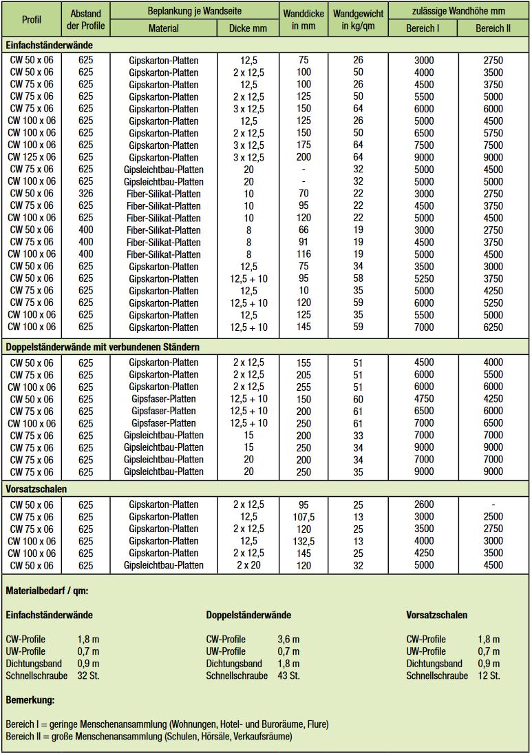
Use a laser, straightedge or chalk line to mark out the course of the wall on the floor and ceiling. Cut U-wall profile UW 75, art. no.: 74400 or UW 100, art. no.: 75400 to length, apply self-adhesive insulating strips, art. no.: 91070 or 91095 to the back and fix to the floor and ceiling. Insert the C-frame profiles CW 75, art. no.: 78250 … 78500 into the U-wall profile UW75 or UW 100 and fasten with drywall screws. Insert insulation if required. Fix GK boards at a screw spacing of 25 cm using drywall screws. Fill and sand the joints flush with the surface.
1.3 Facing formwork with drywall hat profile
The drywall hat profile, art. no.: 9255, is attached directly to the wall surface at a distance of 45 cm using attachment mortar. The profiles must be installed as follows:
1. One profile is installed horizontally in the ceiling and floor area.
The distance to the ceiling or floor should be approx. 5 cm.
2. Depending on the GK panel width, the vertical profiles are then inserted between the horizontal profiles.
A distance of approx. 5 cm should be kept from the horizontal profiles for the installation of empty conduits.
3. Once the mortar has hardened, the GRP panels can be fixed with drywall screws.
4. Fill and sand the GRP joints.
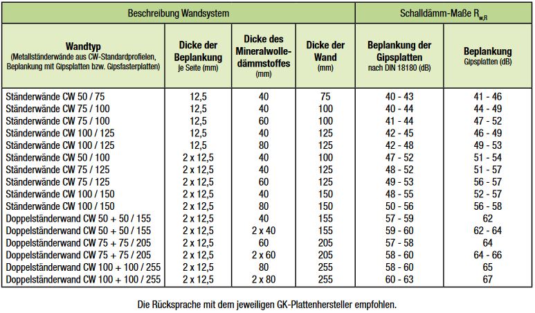
2. free-standing metal stud walls
Use a laser, straightedge or chalk line to mark out the course of the wall on the floor and ceiling.
Cut the U-wall profile UW 50 to UW 100 to length, apply self-adhesive insulating strips to the back and attach to the floor and ceiling.
Insert the C-frame profiles CW 50 to CW 100 into the corresponding U-wall profile UW 50 UW 100 and fasten with drywall screws.
Insert insulation if required.
Fasten GK boards at a screw spacing of 25 cm using
drywall screws.
For double to triple planking, the GK boards must be offset.
Fill and sand the joints flush with the surface.
Please contact us.
Do you need help or have questions about our products?
Do not hesitate to contact us.
We will be happy to help you.